Today we are going to discuss this topic – ‘Network Topology – Easy Classification for Beginners’. In this post, we are going to clear your all Network Topology related doubts, and discuss the advantages, limitations of the topologies, and so on.
This is a very important topic for Computer Science and IT students, and especially for those who are willing to build their career in the Computer Network Architecture Field. So, if you are really interested in this topic then stay tuned with us, and Let’s go.
What Is A Network Topology?
Network Topology is the Physical and Logical Arrangement of the elements (LINKS, NODES, etc.) of a communication network. Nodes usually include devices such as switches, routers, and software with switch and router features. Network topologies are often represented as a graph.
- Network topology can be used to define or describe the arrangement of various types of telecommunication networks, including command and control radio networks, industrial field busses and computer networks.
- Network topologies describe the arrangement of networks and the relative location of traffic flows. Administrators can use network topology diagrams to determine the best placements for each node and the optimal path for traffic flow.
Topologies Are Categorized As Either:
1. Physical Network Topology
Physical Network Topology is the placement of the various components of a network and the different connectors usually represent the physical network cables, and the nodes represent usually the physical network devices.
Physical Network Topology examples mainly include BUS, STAR, MESH, TREE, and RING TOPOLOGY.
2. Logical Network Topology
Logical Network Topology is the arrangement of network devices and nodes to form a logical or physical structure. The logical topology deals with network protocols that are used to control the data flow across the network.
The Ethernet Protocol is the most common protocol used for the Logical Topology. Logical Network Topology examples include TWISTED PAIR ETHERNET, which is categorized as a LOGICAL BUS TOPOLOGY, and TOKEN RING, which is categorized as a LOGICAL RING TOPOLOGY.
Why Is Network Topology Important?
Topology refers to the geographical arrangement of the computers. It gives a pictorial representation or a map diagram of how the different devices in the network are connected. It is similar to a floor plan of a building and hence represents a layout of the network.
Network Topology plays a major role in how a network functions. The layout of a network has a direct impact on Network Functionality. Therefore, choosing the right topology can help increase performance, as a properly chosen and maintained network topology increases energy efficiency and data transfer rates.
Network Topologies Are Important Because:
- The network topology determines the system performance.
- It determines the cable media type used to connect the network.
- Network topology also determines the cost cabling the network.
- Some data access methods can work only with specific topologies.
Simply put, network topology helps us understand the two crucial things. ONE, it allows us to understand the different elements of our network and where they connect. TWO, it shows us how they interact and what we can expect from their performance. For this reason, network topologies play a major role in Computer Network System Architecture.
Classification of the Network Topology
The arrangement of a network that comprises nodes and connecting lines via sender and receiver is referred to as network topology. The various network topologies are:
1. Physical BUS Topology
A BUS Network is a network topology in which nodes are directly connected to a common half-duplex link called a BUS. It transmits the data from one end to another in a single direction. A host on a bus network is called a Station. In a bus network, every station will receive all network traffic, and the traffic generated by each station has equal transmission priority. A bus network forms a single network segment and collision domain. Special connectors called T-Connectors are used to connect a drop cable to the back cable.
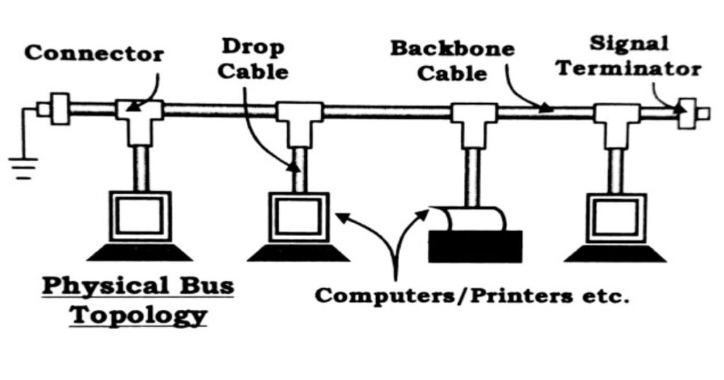
In the case of Bus topology, all devices share a single communication line or cable. Bus topology may have problems while multiple hosts sending data at the same time. Therefore, Bus topology either uses CSMA/CD technology or recognizes one host as Bus Master to solve the issue.
FUNCTIONS:
- Bus topology is used for small workgroup local area networks (LANs) whose computers are connected using a Thinnet Cable.
- Only one node can transmit at a time. If one device wants to access another device, it puts the message addressed to that device in the network.
- All devices receive the message, but only the node whose address matches with the destination address of the message accepts the message.
- Trunk cables connecting hubs or switches of departmental LANs to form a larger LAN. Backboning, by joining switches and routers to form campus-wide networks.
ADVANTAGES:
- Very easy to connect a computer or peripheral to a linear bus and it works well for small networks.
- This topology uses lesser amount of cable length compared to other topologies. Thus it forms the most efficient cabling scheme.
- With the minimum cable length requirement, it becomes a cheaper topology implementation.
- The linear architecture is very simple and reliable and it is easy to extend by joining cable with connector or repeater.
LIMITATIONS:
- Collisions occur in the network resulting in packet loss.
- If any link or segment of the bus is severed, depending on how the system has been designed, all network transmission may fail due to signal reflection caused by the lack of electrical termination. It is difficult to isolate faults in the network.
- It is difficult to troubleshoot such a network.
- The entire network shuts down or is divided into two separate networks if there is a break in the main cable. In addition, Performance degrades as additional computers are added.
EXAMPLES:
10Base5 and 10Base2 Ethernet connections in a Local Area Network (LAN) are examples of the BUS TOPOLOGY.
2. Physical STAR Topology
STAR Topology is the most reliable and widely used topology at present. It is also known as a star network. Star topology is a network topology in which each network component is physically connected to a central node such as a ROUTER, HUB, or SWITCH. In a star topology, the central hub acts like a server and the connecting nodes act like clients.
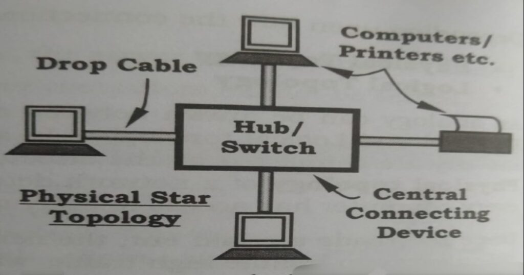
In a star network, every host is connected to a Central Hub. In its simplest form, one central hub acts as a conduit to transmit messages. The star network is one of the most common computer network topologies. Usually, UTP Cable is used with the maximum length of cable between the hub and the node not exceeding 100mm.
FUNCTIONS:
- The star topology reduces the impact of a transmission line failure by independently connecting each host to the hub.
- Each host may thus communicate with all others by transmitting to, and receiving from, the hub.
- When a node transmits a data, the central hub receives the message from the node and transmits it to all the other nodes.
- All devices in the network receive the message, but only the node whose address matches with the destination address of the message, accepts it.
ADVANTAGES:
- It is easy to set up a star network topology. This is because connecting a new node involves only the particular node and the central device like the HUB.
- If one node or its connection breaks, it does not affect the other computers or their connections.
- Devices can be added or removed without disturbing the network and it is easy to monitor and troubleshoot.
- The data gets regenerated while passing through the central connecting device.
LIMITATIONS:
- Expensive due to the number and length of cables needed to wire each host to the central hub.
- The length of the cable required for this topology is greater than required by a bus topology.
- Hub requires more resources and regular maintenance because it’s the central system of star.
- As each device needs to be connected to the central host, if the central device fails then the operation of the whole network also fails.
EXAMPLES:
We connect our PCs, laptops, tablet, and Smartphones to the Wireless Modem for accessing the Internet. Hence, all our devices connect to a single central device known as Hub. So, this is probably the best Example of Star Topology.
This type of topology is usually used with a 10BaseT Ethernet Local Area Network (LAN).
3. Physical RING Topology
In the RING Topology, each device is serially connected in a closed loop or ring pattern, with each node connected to two other nodes. Data travels from node to node, with each node along the way handling every packet. In the ring network topology, the nodes are connected in a closed-loop configuration. Some rings pass data in one direction only, while others are capable of transmission in both directions.
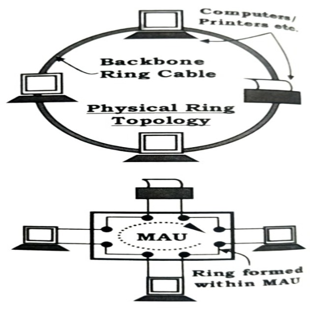
A ring topology is a network configuration where device connections create a circular data path. Each networked device is connected to two others, like points on a circle. Together, devices in a ring topology are referred to as a ring network.
FUNCTIONS:
- A ring topology is a topology for a Local Area Network (LAN) in which every device has exactly two neighbours for communication purposes.
- Typically, all messages travel through a ring in the same direction. A failure in any cable or device breaks the loop and will take down the entire segment.
- To send data, a device has to collect a special electronic message called Token. The message along with the token then travels in a circular manner from one node to the next in a particular direction.
- The station whose address matches with the end address of the data accepts the data and acknowledges its receipt.
- Then it retransmits the data back to the source node, where it is finally removed from the network and the token made free to be used by other nodes.
ADVANTAGES:
- Very orderly network where every device has access to the token and the opportunity to transmit, performs better than a bus topology under heavy network load.
- One station is known as a monitor station which takes all the responsibility to perform the operations. Unlike a star topology, it does not require a central node to manage the connectivity between the computers.
- Due to the point-to-point line configuration of devices with a device on either side (each device is connected to its immediate neighbour), it is quite easy to install and reconfigure since adding or removing a device requires moving just two connections.
- Using STP cables longer distances can be traversed without much signal loss. As only a single station can transmit data at any given time, data collision is absent.
LIMITATIONS:
- One malfunctioning workstation can create problems for the entire network. This can be solved by using a dual ring or a switch that closes off the break.
- Troubleshooting is difficult in this topology, and the addition of stations in between or removal of stations can disturb the whole topology.
- Communication delay is directly proportional to number of nodes in the network.
- A ring network topology is also a little difficult to reconfigure and less secure also.
EXAMPLES:
The IBM Token Ring Network uses this ring topology. FDDI Networks (Fiber Distributed Data Interface is a standard for data transmission in a Local Area Network) also use the ring topology network.
4. Physical MESH Topology
A mesh network (or simply MeshNet) is a local network topology in which the infrastructure nodes (i.e. bridges, switches, and other infrastructure devices) connect directly, dynamically, and non-hierarchically to as many other nodes as possible and cooperate with one another to efficiently route data from/to clients.
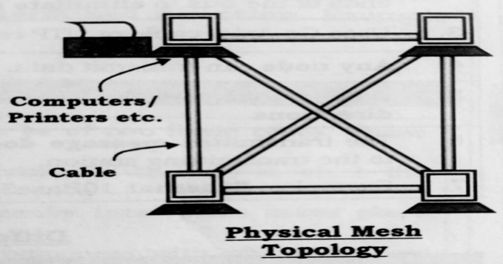
In a mesh topology, there is no central connection point. Instead, each node is connected to at least one other node and usually to more than one through separate cable links. Each node is capable of sending messages to and receiving messages from other nodes. The nodes act as relays, passing on a message towards its final destination.
FUNCTIONS:
- A mesh topology is a network setup where each computer and network device is interconnected with one another.
- It functions like the Bus Topology, where a device accesses another device by putting the message addressed to that device in the network.
- All devices receive the message, and only the node whose address matches with the destination address of the data packet, accepts it.
- This topology setup allows for most transmissions to be distributed even if one of the connections goes down. It is a topology commonly used for wireless networks.
ADVANTAGES:
- As there are multiple connections with alternative paths between two nodes, this is the most reliable type of network topology. Communication within the network is guaranteed.
- Multiple connections mean each node can transmit to and receive from more than one node at the same time.
- Data is reliable because data is transferred among the devices through dedicated channels or links.
- The errors can be easily diagnosed. It provides more security and privacy.
LIMITATIONS:
- Installation and configuration are difficult.
- Complexity and the cost of setting up the network increases with increase in number of nodes.
- Difficult to troubleshoot due to its complexity and the cost of maintenance is also high.
- Many of the connections serve no major purpose. This leads to redundant network points.
EXAMPLES:
One practical example of a mesh topology is the connection of telephone regional offices in which each regional office needs to be connected to every other regional office.
This type of topology is also used in Mission Critical Applications where a fault in the network cannot be tolerated. The Internet uses a Partial Mesh Topology.
5. Physical TREE Topology
A Tree Topology, or Star-Bus Topology, is a hybrid network topology in which star networks are interconnected via bus networks. Tree networks are hierarchical, and each node can have an arbitrary number of child nodes. A tree topology is a special type of structure where many connected elements are point-to-point arranged like the branches of a tree. For example, tree topologies are frequently used to organize the computers in a corporate network, or the information in a database. It is also known as Hierarchical Topology.
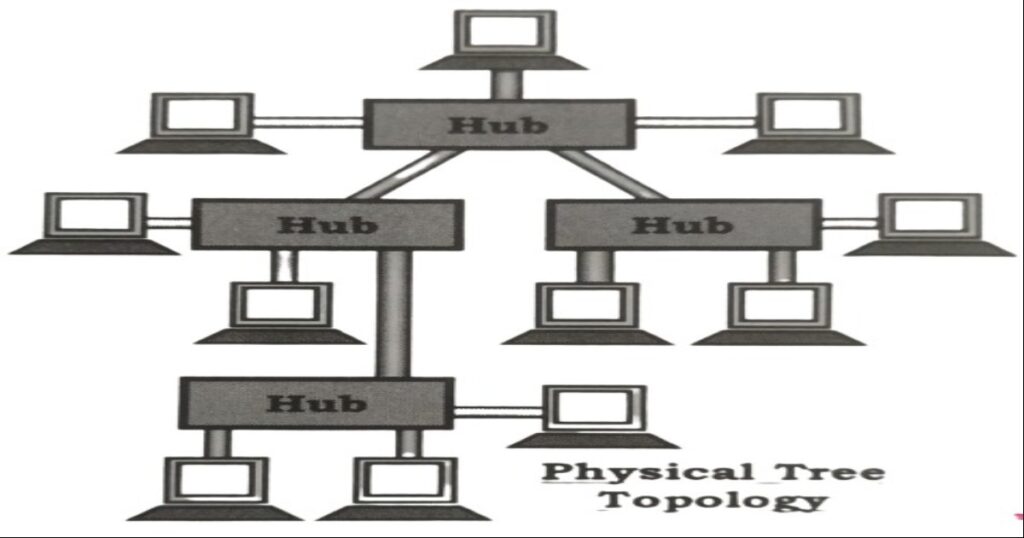
It usually consists of groups of star configured workstations connected to a central hub. This is the most common form of network topology in use presently. This topology imitates as extended Star topology and inherits properties of bus topology.
FUNCTIONS:
- A tree topology combines characteristics of linear bus and star topologies.
- It consists of groups of star-configured workstations connected to a linear bus backbone cable.
- It acts like a Bus Topology. A hub accepts information from one node and sends it to the other nodes and hubs.
- Tree topologies allow for the expansion of an existing network, and enable schools to configure a network to meet their needs.
ADVANTAGES:
- It provides high scalability, as leaf nodes can add more nodes in the hierarchical chain.
- It allows more devices to be attached to a single central hub thus it decreases the distance that is travelled by the signal to come to the devices.
- One of the major advantages of this topology is that when one hub breaks down, only stations connected to that hub get affected. The rest of the network functions as usual.
- Tree network topologies allow for the expansion of an existing network.
- It allows the network to get isolate and also prioritize from different computers.
LIMITATIONS:
- Setting up a tree topology is complicated in comparison to a simple star or bus topology.
- If the central hub gets fails the entire system fails.
- Large cabling is required as compared to star and bus topology.
- The overall cost is high because of cabling.
- Maintenance and configuration of tree topology become difficult due to its large size. A lot of time is taken up for managing point-to-point connections, individual star networks, and identification of errors.
EXAMPLES:
Tree topology is suitable for large networks, spread into many branches such as: Large university campuses, hospitals, etc. This topology is also used in configuring the Domain Name Servers (DNS).
Above We Have Already Discussed The PHYSICAL NETWORK TOPOLOGY In Detail. Now We Are Going To Discuss LOGICAL NETWORK TOPOLOGY In-Depth.
A LOGICAL TOPOLOGY is a concept in networking that defines the architecture of the communication mechanism for all nodes in a network. Using network equipment such as routers and switches, the logical topology of a network can be dynamically maintained and reconfigured.
We have to consider the Logical Topologies after the Physical Layout of a network has been laid. In the midst of network traffic, logical topology helps to maintain an orderly flow of signals in a network. There are basically two types of logical topologies.
These Are: 1. The Logical BUS Topology 2. The Logical RING Topology.
1. Logical BUS Topology
In a Logical Bus Topology, the signals are generated and distributed throughout the network in all directions, irrespective of the location of the intended receiver. The signal contains the address of the destination device. The node whose address matches the destination address accepts the message, while others discard it. The logical bus is used with the physical bus and physical star topologies.
EXAMPLE: In a network physically shaped as a linear bus, the data travels along the length of the cable. The Ethernet uses a logical bus topology in either a physical bus or a physical star. An Ethernet Hub is an example of a physical star topology with a logical bus topology.
2. Logical RING Topology
In a Logical Ring Topology, unlike the logical bus, the signal from a node travels along a specified path in a single direction in a closed loop. This type of topology can be used with a physical ring and a physical star topology.
A logical ring topology can exist in a physical star topology also, as the signal from one node after reaching the hub can be retransmitted from the hub in a predetermined direction.
EXAMPLE: The IBM Token Ring Network.
***** All Pictures Are Taken From The Book – ‘RUDIMENTS OF COMPUTER SCIENCE’, Written By JOYRUP BHATTACHARYA.
Hope you enjoy this article on ‘Network Topology – Easy Classification for Beginners’. If you have any queries, please comment. THANK YOU & DON’T FORGET TO SHARE WITH YOUR FRIENDS Who Need This Informative Article.


sequi enim vel officia at accusamus. consectetur earum nulla laborum sunt nostrum dicta laudantium ipsum magnam dolor placeat velit quae aut eos ipsam. nisi cum magni tenetur accusantium sit beatae. s
id ipsa quas tempore vel ipsam quam sed natus labore eos vero est dolores. neque omnis ratione et eos aliquid assumenda.
Pingback: How to Earn Money Online Without Investment - Techworld18
It’s a pity you don’t have a donate button! I’d most certainly donate to this outstanding blog!
I suppose for now i’ll settle for book-marking and adding
your RSS feed to my Google account. I look forward to new updates and will share this site with my Facebook group.
Talk soon!
Pingback: Difference Between RAM And ROM With Full Information - Techworld18
East or West my bestie is best 😁♥️..BTW great content SHA ..🙂✌️